|
|
The N64 interface project (still alive) |
|
|
|
|
The N64 interface project (still alive) |
Ready made interfaces (and
more) now available !!!
click here for
more info
| Introduction | ||||||||||||||||||||||||||||||||
| Stuff about the N64 controller | ||||||||||||||||||||||||||||||||
| ||||||||||||||||||||||||||||||||
| Contributions & further links | ||||||||||||||||||||||||||||||||
| Disclaimer |
News:
---------12.04.1999: Started selling ready made N64 interfaces.
The N64 pad is a great controller for all kind of games. It is very handy, has plentiful pads and buttons and in addition it provides an analog joystick (in my opinion it's one of the best).
In november 1998 I searched through the www for informations about the N64 controller, because I liked to use it with my PC.
After some time of searching, I encountered that it'll be not easy to interface the controller to the PC because it uses a fast and bidirectional data exchange.
At the end of november I got my own N64 pad (birthday) and started the research.To establish a data communication with the controller, I started with the design of a hardware "request sequence" generator using standard cmos integrated circuits. But soon I had a little cmos graveyard which still doesn't work properly. So I dropped this "project" in it's priority.
In february this year I had the idea to abuse an eprom as a part of the poll sequence generator, with it I was able to build my first working N64 controller interface (which still works reliable with the SNES or arcade driver within SNESKey). But it's still a complicated design (you can see it in the "history" section).
To shrink the circuit together I tried to find an approach using PICs (little microcontrollers from microchip).
In the meantime Earle F.P.III (the guy who makes this tremendous: dpadpro driver) mentioned that there is someone in Great Britain who tries to solve everything with software. So I came into contact with Simon Nield. He had problems processing the incomming data through the printerport, and I had problems with the amount of hardware I used for the request sequence.
So we put our ideas together and developed the now available interface.
We use the output of the printerport to generate the commands for the N64 controller and a small circuit to store the incomming data (so it could be read out at a slower speed through the printerport).
So you can find at this page the circuit of the interface and informations about how to build it, two test programs ("C" and assembler) and the links to Benji Yorks (SNESKey) and Earle F.P.III's (dpadpro) site.
Benji and Earle now have the info about the circuit and the driver developement is in full progress, most likely they release the drivers within the next days.
![]()
Stuff about the N64 controller
The data exchange between the controller and the host:
The N64 controller has only 3 cables to connect to the N64 console. A red one for the power supply (Vcc +3,6V), a black one for ground and a white one for the data exchange.
The data exchange through the "data wire" is bidirectional and could be driven by an open collector device (as the N64 controller itself does).
In its idle state the data line is high ( 3,6 V).
Each bit that is transmitted takes 4 オs of time. When a bit is send to, or from the controller, it starts with pulling data to low (0 V). If the bit has the value "0", the data line remains 3 オs low and then rises to high for 1 オs. If the bit that should be send has the value "1", the data line remains only 1 オs low and rises high for 3 オs.
The N64 controller needs to be polled through the host.
So a "request sequence" must be send to the controller.For the simple data polling (buttons and joystick), sending a 9 bit value : "000000011" to the controller is necessary.
If someone has more informations about the commands that could be send to the controller, please inform Simon or me about it !!!
Immediately**) after the request sequence, the N64 controller starts to transmit its data.
It starts with the value for the "A" button, proceeds with the "B" button and transmits at last information the y-axis value for the analog stick:**) unfortunately this "immediately" is not constant and causes a jitter to the incomming data.
bit data for:
1 A 2 B 3 Z 4 START 5 UP 6 DOWN 7 LEFT 8 RIGHT 9 unused 10 unuesd 11 L 12 R 13 C-UP 14 C-DOWN 15 C-LEFT 16 C-RIGHT 17-24 X-AXIS 25-32 Y-AXIS 33 stopbit For each button a "1" represents a pressed button, and a "0" means: button released. Now for the values of the analog stick:
The data seems to be appear in a signed format. For the x-axis for example it looks like the follwing:
position: bit 17 bit 18 bit 19 bit 20 bit 21 bit 22 bit 23 bit 24 left edge 0 1 1 1 1 1 1 1 ...... 0 x x x x x x x 0 0 0 0 0 0 1 1 0 0 0 0 0 0 1 0 left 0 0 0 0 0 0 0 1 middle 0 0 0 0 0 0 0 0 right 1 1 1 1 1 1 1 1 1 1 1 1 1 1 1 0 1 1 1 1 1 1 0 0 ...... 1 x x x x x x x right edge 1 0 0 0 0 0 0 0 It seems that I can't reach the highest and the lowest values for the x- and y- axis with my N64 controller.
The same format is valid for the y-axis (obviously), where the corresponding data is transmitted from bit 23 to 32.
The stopbit is always "1".
If you count together the times for the polling sequence (9*4 オs) and the returning data (33*4 オs) you get 164 オs at all for the bidirectional data transmission sequence. If you now immediately send the next request sequence to the controller you will receive.... nothing. The controller needs approximately 200 further オs to be ready for the next poll cycle.
![]()
How it works:
All the data lines of the printerport supply the N64 controller with power through diodes. The two cmos 4006 are supplied directly through D7.
To send data to the N64 controller, D0 needs to be pulled low as required (see the chapter above for the timing of the interface) for the data transmission.The two cmos 4006 form a 33 bit shift register.
The incomming data reaches the shift register through two different tracks. The first path leads through the 4.7 k resistor, where the falling edge of the incomming signal is used to clock the shift register. At it's second path, the signal passes the R/C (10k /100pF) link, which integrates the signal. So in the moment of the falling edge (clock), there is a "high" voltage at the input of the shift register if the bit send was "1" and a "low" voltage if the corresponding bit has been a "0".
At this picture you can see the voltages at the data input of the shift register (upper beam) and the clock input (lower beam):
10 オs / div
2 V / div
If the data is stored into the shift register, it could be dumped to the PC through the output of the second 4006.
For this, the PC needs to pull D1 to low 33 times (the PC generates the 33 clock pulses).By the way, my N64 controller runs with this circuit at the weak printerport of my spare PC with only 2,6 V.
Connect 2 N64 controller interfaces to a single printerport:
Now you may ask: Can I attach two N64 controllers to my computer ?
And the answer is: YES ! You can.You can do this in two ways:
1. If your computer has two printerports, just attach the second controller with it's interface to the other printerport and install another instance of the dpadpro driver (at joystick ID#2).2. If you have only one printerport available, you need the following Y-adaptor and a new release of Earles dpadpro 4.9 (build 4.9.0.276 or higher).
But remember: At the moment, UltraHLP supports only 2 players with 1 joystick and 1 keyboard.
But today I just send two interfaces to the denuclearized crew, and I'm sure that they'll provide full dual-player mode with two joysticks in one of the next releases.
As you can see from the schematic, you will need an additional power source because a single printerport is not able to supply two N64 controllers with power.
To "pick up" the required +5V from your computer you have several possibilities. A good idea is to use pin 1 at the gameport, or pin 4 at one of the ps/2 ports. If you have an older computer with DIN5 connector for the keyboard, you can use pin 5 of this connector.
If you like, you could even use a 4.5V battery as power supply or a stabilized external power supply.... or you can get the +5V from inside of your PC (from an unused power connector inside)..... or.... or.....
Connecting more than 2 controllers/interfaces to a single printerport.
With dpadpro 5.0 you can use up to 4 n64 controller interfaces at a single printerport.
The schematics for the required "double-Y-adapter" is similar to the scheme above, but obviously you need two more female DB25 connectors (and some wire).Here's how to build the 4x adapter:
signal name pin at printerport pin at female db25 #1 pin at female db25 #2 pin at female db25 #3 pin at female db25 #4 shift-clock 3 3 3 3 3 data-out pad#1 2 2 - - - data-out pad#2 4 - 2 - - data-out pad#3 5 - - 2 - data-out pad#4 6 - - - 2 data-in pad#1 10 10 - - - data-in pad#2 12 - 10 - - data-in pad#3 13 - - 10 - data-in pad#4 15 - - - 10 GND (ground) 18 to 25 18 to 25 18 to 25 18 to 25 18 to 25 power (+ 4,3V) *) 9 9 9 9 *) You can get the required 4.3V through a single diode from your gameport, keyboard-connector or ps2/plug as described above.
Hey, we found a cool page where someone describes in detail how to build the Interface. Unfortunately the site is in spanish, but it has plenty of excellent pictures which could be understood without the knowledge of this language.
I will put the pictures here at my website, with english text in the next days. In the meantime take a look at dev's website at emulatronia.
Unfortunately the N64 controller uses no standard connector. Nintendo uses a proprietary 3 pin plug for it
.
Now there are different ways to "connect" the controller to the circuit.An elegant way is to hack a N64 extension cable, but these parts are quite expensive (12 - 15 $ at my site).
The simplest way (not recommended !) would be just to cut off the connector and solder the wires directly to the interface, but then you can't use the controller any more for your N64 console.
So I used another way: I just inserted a pair of DIN 5 connectors (male and female) at the end of the N64 cable, so I can still use it for an N64 if I plug both connectors together, or I can plug it into the interface circuit where I assembled a DIN 5 pin female connector for pcb assembly (like the standard keyboard connector at motherboards). In addition this solution has the advantage that you can use a cheap keyboard extension cable with the N64 controller.
Here you can see the female DIN 5 pin connector (for print assembly) at the side of the interface:
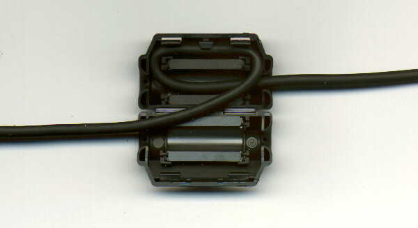
At the end of the N64 controller cable there is a filter assembled (the cable just forms a little coil through a ferrite core) to minimize radio interferences. If you want to insert a male/female pair of connectors, it's a good idea to move the filter a few inches towards the controller, so that there'll be enough space to mount the plugs.
It's a little tricky to open the snap-in mechanism, but two little screwdrivers and a pocket knife will do the job.
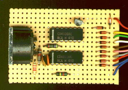
Here you can see the standard circuit assembled on an experimental board :
component side
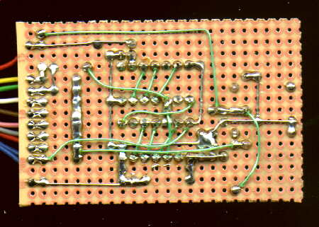
soldering side
At the left you can see the DIN 5 pin connector which leads to the N64 controller. In the middle there are the two cmos circuits, at right you can see the diodes and the cables leading to the SUB-D 25 pin connector (male).
If I'll find the time I make a small pcb. If it's ready, you'll find it here.
Here you can see now Simon's design:
If you have a closer look at it, you'll see that Simon only uses 4 diodes for the "power supply" of the N64 controller. Furthermore he has not fitted the transistor. You can do this if your printerport is sensitive enough (just connect pin 10 of the printerport to pin 9 of IC-2.
You can see only a single cmos 4006 at the picture, your eyes don't fool you. Simon mounted both circuits like a little "sandwich" (piggy-back design) while he spread away all the pins (except pin 14, 7 and 3 which needs to be connected together).
Design studies for a "ready made interface"
Many of you have been asking me if I could provide some ready made interfaces.
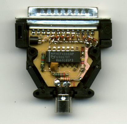
So I'm now working on it.Here you can see the first possible solution of such an interface:
As you can see, the circuit fit's into the hood of an "normal" DB25 connector. It uses a very small double sided pcb (which is going to be optimized a little bit).
The cmos circuits are assembled "smd - like". You can't see the second one, because it is assembled at the bottom of the board.
As connection to the N64 controller I used a standard mini DIN connector (like the one for ps/2 mices and keyboads). But it's also possible to attach a hacked N64 extension cable to it.
Here you can see the upper copper layer.
And now a "look through" to the bottom layer.The design still needs a little bit of optimization. Especially the pcb could look a little bit more professional. I made the pcb yesterday night in my kitchen
. I had no possibility to make real junctions at the board, so I needed to solder the parts at both sides (that's why I lost approximately 1mm in height for the diodes..... and now, after closing the hood, they look a little bit "crunched").
So if you would like that I go into that direction, please mail me ! Tell me what you think, if you like it or not.
And tell me how much it's worth for you (be honest please) if I'm going to sell it once.
I'm especially interested if you would prefer to pay 5$ more if I use an attached N64 cable instead of the DIN ones
(I already received an email from a norwegian guy, who would like to give me 50$ for such an ready made interface, but I expect that it'll be much cheaper).I don't know when it'll be ready, but my actual pcb source needs at least 14 days.
If you have further informations about where I can get those N64 extension cables for a good price, or if you have someone who could manufacture double sided pcbs for cheap (maybe yourself), please mail me too.
| Standard circuit: | |
| 2 * cmos 4006 | IC1, IC2 |
| 10 * standard diode (like 1N4148 or similar) | D1 - D10 |
| 1 * resistor 4.7 k, 1/4 watt or less (yellow, purple, red) | R1 |
| 1 * resistor 100 k, 1/4 watt or less (brown, black, yellow) | R2 |
| 1 * resistor 10 k, 1/4 watt or less (brown, black, orange) | R3 |
| 1 * resistor 2.2 k, 1/4 watt or less (red, red, red) | R4 |
| 1 * capacitor
|
C1 |
| 1 * transistor standard pnp-type, like BC559 or 2N3906 | T1 |
| 1 * experimental board (single pads) | |
| 1 * DIN 5 pin connector female for print assembly | |
| 1 * connector DB25 male | |
| For the N64 controller cable: | |
| 1 * DIN 5 pin connector male | |
| 1 * DIN 5 pin connector female | |
| or: | |
| 1 * DIN 5 pin connector male | |
| 1 * N64 extension cable |
At the moment there are two test programs available:
N64pad.zip from Simon Nield.
Press "1" and "2" to change the printerport. Press +/- to change the timing delay.
To change the command being sent use the '[' and ']' keys (change-inventory item).
Commands known so far;
00 = get status
01 = read button values
02 = read from mempack
03 = write to mempack
ff = reset controller
04 = read eeprom
05 = write eeprom
N64_0278.com, N64_0378.com and N64_03BC.com for the different printerport adresses (click here for the assembler source). It's not as cool as the one from Simon, but it's short and reliable.
Best would be if you run it in a fullscreen !!! DOS box (so you could close it through windows).
Just launch the program in a fullscreen DOS box. Each incomming bit is indicated with a "1" if set and with a "0" if not.
You can see the stopbit (33th bit) which is always set. Furthermore you can detect the C-UP and C-LEFT buttons pressed at the N64 controller.
To close the program, you need to close the DOS box manually (the program itself runs in an endless loop).As already mentioned in the introduction, Earle F.P. III and Benji York are currently updating their programs/drivers for the interface.
Finally I was able to figure out how the rumble-pak is going to be accessed.
I checked the data line while the N64 generates an "rumbling" event with my tektronix scope. The sequence to switch the rumble motor on and off was easy to find (because it was a repetitive event which could be displayed by the scope).
Then I made a little test program that reproduces this sequences. The controller (with the rumble-pak attached) responded at the data line exactly as he should (and as he did at the original N64), but that %&$% rumble-pak refused to rumble.
So there must have been a short "initialisation" sequence, which enables the rumble-pak functionality at the controller.
To "catch" this short sequence, a friend helped me out with an HP Logic analyzer to observe the data communication between the N64 and the controller, but the memory depth of the Logic analyzer was to small to catch everything of interest. After hours of successless measuring, we encountered that we would never be able to catch the sequence with the available modules and memory.
So I borroughed a transient recorder (able to store 2 channels with a duration of 65 ms (1オs per sample)), and I was lucky to catch the missing initialisation sequence for the rumble-pak.
Now you can download my small assembler test utility with rumble-pak support.
To send the "initialisation" sequence just press the <START> button (the ? changes to an "i" then).
To switch the motor on for a short time, just press the <A> Button, to switch it off, simply press <B>. That's all.
Remember to run the testprogram in a full-screen DOS box.
Test program for LPT1: rumbl378.com LPT2: rumbl3bc.com LPT3: rumbl278.com
Because daily we have hundreds of emails begging for the direct-x drivers (dpadpro), Earle was so kind to "pre-release" version 4.9 of his incredibly cool program !!!Be thankful now, and do not disturb him with your bugreports, wishes and further ideas (especially don't ask for rumble pack support right now) until the end of march !!!
He is just in preparation for his final exams. And we all wish him the best for it. So cross your fingers now and support him to succeed by beeing patient and giving him the time for his preparations.Oops, nearly forgot the link
ps: Before installing dpadpro4.9 remove previous versions of dpadpro from your computer. And in addition, to ensure that the driver works properly (and the axis and buttons are displayed correct), it's a good idea to restart your computer after installation.
Great !!! There is a new driver available for our interface.Actually it's only a beta-release (0.9) which only supports 1 controller at LPT#1 (I/O 0378h).
It has been written for Windows 98, but works good for Win95b too (at least here at my site).You can download Jemy's DirectN64 pad driver here: Jemy's DirectN64 driver.
Stay tuned at this site !
New (18th of april'00):
There's now beta-release 0.95 available, which provides a generic rumble/force-feedback support.
![]()
Due to the numerous emails I get each day since we released the circuit, I just added this section.
In the moment I have my problems in "processing" all the mails, so be patient, "I'll do my very best".Q#1: When will the DirectX driver (dpadpro) be ready ?
A#1: I don't know exactly, but I expect that it'll be released within the next days. I have a good working ゚-version from Earle right now (I goes without saying that I don't give it away) but the driver is still in developement (see Q#3). Earle just send me an update this night (03.03.99).
Q#2: Can I buy a ready made circuit (from you)?
A#2: At the moment: No.
But because this is one of the most frequently asked topics, I'm just doing some "case studies" about which design should be the best "for reproduction". So I assume that I'm going to provide some kind of "kit" and/or ready made ones, but this will take some time too.
Q#3: Is the circuit ready ? Or is it still in development ?
A#3: We thought that the circuit is ready, that's why we released it.
But in the meantime we encountered at some systems problems related to a jitter at the output of the printerport (caused by DMA and bus activities). This caused the controller to work unreliable at these systems ("ghost button presses").
We try to solve the problem by software, but it might be possible that we need to make a small modification to the circuit.
So "stay tuned" !Q#4: Will it be possible to use the N64 controller with the interface together with UltraHLE (for "the real N64 feeling") ?
A#4: Simple answer: Yes !
(Many thanks to the denuclearized crew for their quick update (10 button UltraHLP))
1. build the circuit and interface, connect it to the controller and the pc.
2. install the direct-x driver (dpadpro) following the "Software installation" section into the readme.txt which comes with dpadpro49.zip. Choose the "N64 4 axis" or "N64 analog" driver within Earles package.
3. patch a fresh copy of UltraHLE.exe with the little utility UltraHLP 2.0 (get it from the denuclearized crew).
You need to assign the buttons in the following way:
Don't forget to press the "Patch.exe" button !
4. Now enjoy UltraHLE with your original N64 controller. Which simply gives the best "original feeling".
If the "denuclearized crew" now adds support for 14 buttons (hey guys, what do you think about it ? UltraHLP 2.1 ???), you can gain complete N64 controller support by choosing "N64 analog" as driver.
Q#5: What is the little triangle with the thick line in the circuit, and what is this curious part marked with T1...... ?
A#5: Sorry guys, but if you aks this type of questions it'll be better to find some friend with some electronic knowledge who can build the circuit for you (or just wait till A#2 is ready).
By the way, I think it's always good to have a little project together with some friends. It's fun, you learn something and it's better as hanging at your PC playing Quake, Metal Slug 2 or something similar for hours and hours.....
Q#6: I can get all the parts, except the 4006 cmos type chip. Is there an alternative ?
A#6: The 4006 is a standard cmos circuit. It's one of the "40"er cmos logic family. Every well sorted electronic shop (the type of shops that sells transistors, connectors, kits and so on... not the one that sells refrigerators or popcorn machines) should be able to provide them. Unfortunately there is no substitute for this part.Q#7: To which pins of the cmos 4006 is D7 connected ? And which pins of it are connected to ground ?
A#7: I just forgot to add it in the scheme. Vcc of the 4006 is pin 14 (so both pin 14 are connected to D7).
GND is pin 7.
Q#8: I rebuild the circuit but it didn't work. What's wrong ?A#8:
1. Check the voltage at the N64 controller (while it is attached to the interface, between + Vcc and GND). If it's below 2.7 V you need to supply the circuit in another way. You can do this for example by getting the +5V from the gameport connector (pin 1) and connecting a further diode in serial between this pin-1 and everything that has been previously connected to pin #9 of the printerport (the diodes "facing" into the "direction" of the interface).
2. Be sure that your printerport is enabled correctly (into the bios or by jumper, SPP will do, but EPP or ECP works too).
3. Do not overclock your ISA bus ! Because the timing of the printerport is derivated from it !!!
4. If #1 - #3 are ok, you probably made a mistake by rebuilding the circuit. Check every connection ! Check the values of the parts you used. Take care not to overheat the integrated circuits during soldering. Beware of static chargement when messing around with the cmos parts.....
Q#9: The circuit works.... somehow... It has a strange behaviour ?
The buttons didn't respond properly. The only button that works is button "A".... If I keep button "A" pressed, then button "B" works too... and so on.A#9: This sometimes happen (I received 3 emails with the same content), we don't know exactly why. I have two suggestions to solve the problem:
1. Use a 180 pF (or even 150pF) capacitor instead of the 220 pF. The values of the ceramic capacitors sometimes are up to 80% higher than they should be.2. A little bit more tricky, but it solves the problem secure: remove the 100 k resistor from the circuit. Add a 47k trimming potentiometer, where one end is connected to ground and the other is connected to +Vcc. Then connect the tap of the potentiometer through a further 10k resistor to pin 1 of the first cmos 4006 (to the point where you removed previously the 100k resistor). With the trimming potentiometer you can now adjust the dc-offset at the input of the first shift register.
You'll then find a "range" where everything works perfect; adjust the trimmer to the middle of this range.3. Last, but very unlikely: refer to the "Disclaimer" section ...... (we did not guarantee the functionality in any cases).
Q#10: Why have you choosen the printerport ? Wouldn't it be better to use the gameport or the USB ?
A#10: As you can see from the descriptions of the interface above, the N64 controller requires a very fast and bidirectional data communication to be accessed. Even if we abuse the MIDI port (available at the majority of soundcards) for the output purposes, it would be too slow ! The minimal required pulse length is 1オs.
A fast enough interface would be the USB port. But if we would have choosen it for the I/O purposes we needed to program the USB chip (and as far as I know there are several types available) directly, so the USB would have been lost for further devices.
Another possibility would have been to add some intelligence to our circuit which could handle the USB protocol, but this would have blown up the circuit to much.
Q#11: What do I need to play with two N64 controllers at a single PC ?
A#11: First you need dpadpro release 5.0 (or higher). Then you obviously need two interfaces.
Now you have two possibilities:1. If you have two printerports available at your PC, you just can use each of them for a single interface.
2. If you have only one printerport available, you need the Y-adapter for the printerport (as described above),
it allows you to connect two interfaces to a single printerport.
Furthermore the Y-adapter get's the power for the circuits (and the controllers) from the keyboard port (so if you order an Y-adapter, don't forget to tell me if you have a ps/2 or a AT type keyboard connector.
Q#12: Can I attach more than 2 N64 controllers to my PC ?
A#12: Yes, it's possible to connect up to 4 interfaces to a single printerport.
Q#13: I really like the informations and the stuff at this page, can I set up a mirror for this page ?A#13: To be honest, I don't like this Idea. You could drop a description about the things which could be found here and a link to this site (that's welcome).
Or you can provide additional informations, like "Dev" from emulatronia did with his "how to build the interface" page.
Q#14: Is the pcb layout for the ready made interfaces public available ?A#14: No. As you can imagine it's not my intention to provide everything nescessary to copy my "ready made" interfaces.
Q#15: I really like that interface and want to produce and sell them. What do I need for it ?A#15: As you can see in the disclaimer section the circuit is free for private use, but if you want to use it in a commercial way, you need an agreement with us. The conditions for this agreement are very moderate. Furthermore it's good to know that we give no exclusive agreements and that the "court of jurisdiction" is Seligenstadt/Germany.
Last but not least a little request to all of you:
Please try to mail me in english, german or maybe french (where I would have still problems).
Because I don't speak portuguese, spanish, dansk ......
(but I really like to get emails from all over the world)
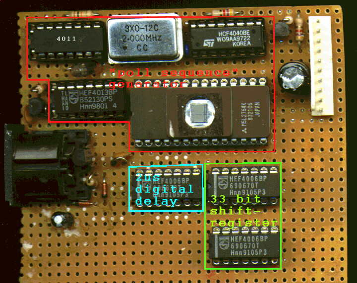
My first successfull project to interface a N64 controller to the PC, using the printerport:
It's fast, reliable and works just great ! It could be "seen" by the PC like a standard NES/SNES type gamepad with 32 bits instead of 8/12. But it's not easy to rebuild it, if you have less knowledge in these things.
component side
the "red" area marks the part of the circuit which generates the "request sequence"
the light blue area is a cmos 4006 which acts as a 2 オs digital delay line
the green part is the 33 bit shift register which simply stores the information from the controller, so that it could be read out by the pc in the same way the NES/SNES pads are polled.
Here how the circuit works in brief:
The EPROM stores the bit sequence for the request cycle, while each microsecond uses the lsb of 2 following bytes. The msb of the EPROM data is used to stop the cmos counter (4040 and QOSZ) which generates the address lines for the EPROM.The counter could be restarted through a transistor and a gate (1/4 4011) while pulling the "reset" line to high for at least 1 オs (pin 3 of the printerport).
The bidirectional data is split by two transistors for each direction, while the lsb from the EPROM drives one transistor (through a latch (1/2 4013), so that only valid data appears). The other transistor seperates the incomming data which is then be feed through the 2 オs digital delay line. The undelayed incomming data is passed to the following 33 bit shift register (2 * 4006 in series) while the delayed data drives the clock line of the shift register.
So the "data" (33 bit wide) is stored, and ready to be read out through the shift register, after it's transmission from the N64 controller.
Using one of the NAND gates inside the 4011 it is now possible to shift out the data of the shift register while a clock pulse is provided from the PC (pin 2 of the printerport).
The output of the shift register is connected to pin 10 of the printerport, to read out the data.If you are interested in the sheet and the eprom dump of this approach, feel free to mail me.
But now, it's no longer nescessary. It was an interesting research object and provided a lot of informations.
First I would like to thank Simon Nield, Earle F.P. III and Benji York for their informations, suggestions and quick responses !!!
Furthermore thanks to:
- my ex-wife and the guys at
(for my birthday gift)
- "Yamada" for the infos at his site
- the "saint" for his site and for telling me that the time for the N64 interface has come now
- LaC at dextrose for the info about further controller commands
- the "denuclearized crew" for their UltraHLE patch program (called: UltraHLP) which makes it possible to use the N64 controller (together with the DirectX driver) within UltraHLE
All the informations at this site are provided as they are. I'm not responsible if you burn your fingers or something else with the soldering iron or if you damage your computer or N64.
Furthermore: The hard- and software has been tested at several systems together with a genuine N64 controller and it works good for my fellows and me, but I do not guarantee their functionality.
You can use the interface (or parts of it) free for non commercial interests. If you want to use some parts for a commercial product (e.g. interface kit), you'll need our agreement.
For all the software parts the GNU General Public License is valid.
N64 is trade-mark of nintendo.
If you have more informations or suggestions, feel free to mail me:
